 EA4FSI
| Type | Two-wire broadband dipole |
|---|---|
| Design | Australian |
| Impedance | 300 Ω |
| Simulation | 4NEC2 |
| Band | 3–30 MHz |
| Remarks: Resistive and inductive loading. | |

1. Antenna design and modelling
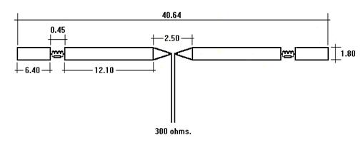
Fig. 1 shows the dipole design. All dimensions are given in metres. Starting at the feedpoint, each antenna arm is constructed as follows:
-
At a distance of 1.25 m from the feedpoint, the two wires in each arm are separated by 1.80 m. A metal spacer is installed at this point to keep the wires parallel.
-
From the first spacer, both wires extend 12.10 m to the next metal spacer.
-
A 0.45 m gap separates this section from the next section of the arm.
-
The next section also consists of two wires, with a metal spacer at each end. This section is 6.40 m long.
-
The two sections are connected by a carbon resistor (330 Ω, 2 W) and an inductor (16 µH), connected in parallel. AMSAT Argentina provides useful tools for designing inductors.
All conductors are copper wire with a diameter of 1 mm. The antenna uses eight metal spacers, each 12.5 mm in diameter. The maximum power applied to the antenna must not exceed 350 W.
Fig. 2 shows the antenna model in 4NEC2.
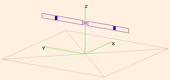
The antenna has a feedpoint impedance of approximately 300 Ω across most of the 3–30 MHz band. A 6:1 impedance-ratio balun can be used to connect it to a 50 Ω coaxial feed line. The actual match will depend on the antenna impedance at each frequency.
2. Simulation results
This section presents the 4NEC2 simulation results, including standing wave ratio (SWR) and radiation patterns.
2.1 Standing wave ratio (SWR)
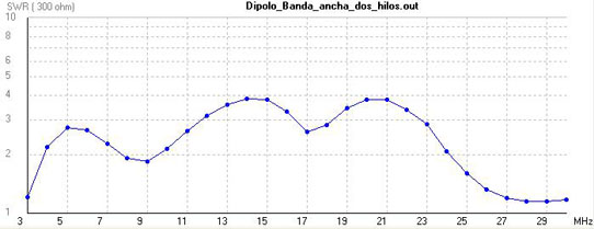
SWR was calculated using a reference impedance of 300 Ω. An antenna tuner may be necessary in some installations, particularly when the antenna is close to metal objects.
Fig. 3 shows the simulated SWR across the 3–30 MHz band, referenced to 300 Ω.
2.2 Radiation patterns
-
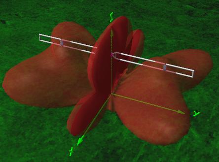
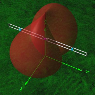
80 m band: The antenna exhibits a bidirectional radiation pattern (Fig. 4), with its main lobes perpendicular to the antenna axis and a gain of approximately −0.76 dBi. It also supports NVIS propagation, with a simulated gain of −0.76 dBi.
-
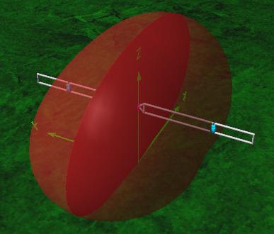
40 m band: The antenna exhibits a bidirectional radiation pattern (Fig. 5), with its main lobes perpendicular to the antenna axis and a gain of approximately 0.76 dBi. It also supports NVIS propagation, with a simulated gain of −0.78 dBi.
-
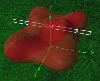
20 m band: The radiation pattern has four main lobes oriented approximately 30° from the perpendicular to the antenna axis (Fig. 6), with a gain of about 3.26 dBi.
-
17 m band: The radiation pattern has four main lobes oriented approximately 55° from the perpendicular to the antenna axis, with a gain of 8.24 dBi, and two secondary lobes perpendicular to the antenna axis, with a gain of 4.43 dBi (Fig. 7).