
Sloping Vee 470
|
Main → HF Radio Resource Center → HF Antennas → Sloping Vee 470 |
![]() Este artículo también está disponible en Español (this article is also available in Spanish).
Este artículo también está disponible en Español (this article is also available in Spanish).
![]() Abstract:
Abstract:
This article describes the design and simulation of a multiband Sloping Vee antenna for the HF band, using the software MMANA-GAL. The simulations are focused to obtain the impedance and the radiation patterns of the antenna between 2 MHz and 20 MHz.
 |
Type: Inverted V dipole |
| Design: N/A | |
| Impedance: 235 ohms | |
| Simulation: MMANA-GAL | Band: Multiband |
Remarks: Design with 470 ohms resistive loads. The antenna requires a 4:1 balun. |
|

Sloping_Vee_470
Simulation report of the Sloping Vee 470 antenna
Sloping_Vee_470_report.pdf
1. Design and antenna modeling.
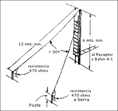
In this sloping vee design, each leg has a length of 12 meters and a resistive grounded load of 470 ohms (fig.1). The heigth of the mast must be of at least 6 meters. The transmission line should be of a ladder type, with adequate impedance, and requires a 4:1 balun. It is recommended to use an antenna coupler, especially for ALE operation.
The fig.2 shows the antenna modeled with MMANA-GAL.
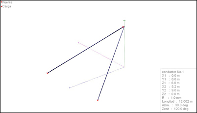
The feeding point is located in the "Z" axis, at a height of 6 meters. This is the departure point for the legs of the dipole, forming a 30 degrees angle whose bisecting line is the "Y" axis. The 470 ohms resistive loads are located in the opposite side of each leg.
2. Simulation results.
In this sections the results of the simulations with MMANA-GAL are shown: calculated standing wave ratios (SWR) and radiation patterns for each band.
2.1. Standing wave ratio (SWR).
The fig.3 shows the calculated SWR for a characteristic impedance of 200 ohms, corresponding to a transmitter with 50 ohms of output impedance and a 4:1 balun.
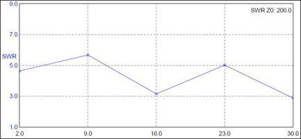
Although the SWR level is low, we can see that it is necessary to use an antenna tuner.
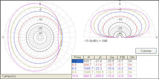
2.2. Radiation patterns.
The fig.4 shows the radiation patterns calculated at frequencies between 2 MHz and 10 MHz.
The fig.5 shows the radiation patterns calculated at frequencies between 10 MHz and 20 MHz.
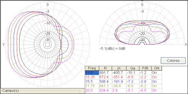
This is a directive antenna but with low front-to-back ratio. The radiation maximum is achieved at the bisector of the angle defined by the two arms, with losses in the whole band which are more pronounced at lower frequencies. Although this is a quite inefficient antenna, it has the advantage of a low SWR in all the HF band. Not recommended for NVIS operation due to its low gain at low frequencies.
|
Ismael Pellejero - EA4FSI |
 EA4FSI Home |
 HF Antennas TOC |
 HF Central |