Analysis of HF Monopoles
|
Main → HF Radio Resource Center → HF Antennas → Analysis of HF Monopoles |
![]() Este artículo también está disponible en Español (this article is also available in Spanish).
Este artículo también está disponible en Español (this article is also available in Spanish).
![]() Abstract:
Abstract:
In this page you will find an analysis of several monopole configurations, the differences between a perfect and an imperfect ground and the effects of using a ground plane made of radials or counterpoises. The analysis are based on simulations performed with the 4NEC2 software and are performed introducing new elements in successive aproximations.
Table of contents:
1. Monopole over perfect ground.
2. Monopole over real ground.
3. Monopole with one radial or counterpoise.
4. Monopole with 4 radials.
5. Conclusions.
| 4Nec2 simulation downloadable files: |
| Ideal monopole over perfect ground Monopolo_ideal.nec |
|
| Monopole over average ground Monopolo_tierra_media.nec |
|
| Monopole over average ground, 1 radial Monopolo_tierra_media_1radial.nec |
|
| Monopole over average ground, 4 radials Monopolo_tierra_media_4radiales.nec |
|
| Monopole over average ground, 32 radials Monopolo_tierra_media_32radiales.nec |
1. Monopole over perfect ground.
The antenna under analysis is an ideal quarter-wave monopole designed to work in the 20 meters band, adjusted to a central frequency of 14,1 MHz. In a first approach, an ideal monopole over perfect ground is analyzed. Then, an imperfect ground is introduced and after that the effects of adding radials to achieve an improved ground plane.
1.1. Antenna design.
In 4NEC2, we simulate the monopole along the "Z" axis, perpendicular to the "XY" plane (fig.1).
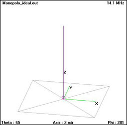
In this first analysis we consider a perfect ground and zero radials. The monopole length, as optimized with 4NEC2 to minimize SWR, is 5,16 meters.
1.2. Simulation results.
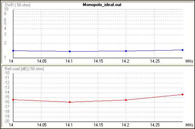
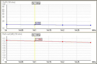
The resulting SWR is 1:1,38 in the whole 20 meters band, as shown in the fig.2.
The antenna is omnidirectional, thanks to the simulated perfect ground plane, and its gain is 5,15 dBi (3 dBd), that is, twice the gain of a half-wavelength dipole (fig.3).
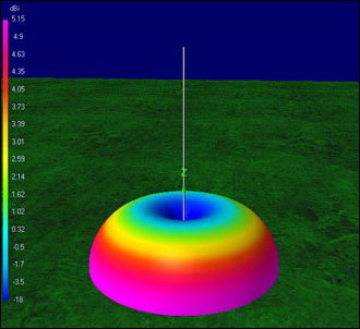
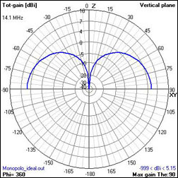
In the vertical plane, the radiation pattern has its maximum gain just at a null takeoff angle, making the antenna optimal for DX work under these ideal conditions. The radiation efficiency, as calculated by 4NEC2, is 99,96 %, very close to the theoretical 100 %.
2. Monopole over real ground.
Using the same design (fig.1), the perfect ground is changed by a real average ground (conductivity 0.005 S/m, dielectric constant 13) in order to analyze the effects on the antenna parameters. This will help to move the theoretical analysis to the real world
2.1 Simulation results.
Using the same length of 5,16 meters, the SWR rises to 1:14,5. That is, the antenna is unmatched with an impedance far away of 50 ohms in its feeding point. It will be necessary to use an impedance transformer or an antenna tuner.
Although the antenna is still omnidirectional, the first observed effect of an imperfect ground is an elevation of the radiation lobe (fig.6).
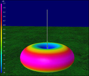
This effect is typical in antennas installed on the side of the roof o a vehicle (finite ground plane): towards the vehicle roof the ground plane is optimal and the radiation pattern is not as distorted as in the other way, where the absence of a ground plane causes the antenna lobe to be higher (fig.7).
The new antenna gain is -7,74 dBi at a takeoff angle of 25 degrees over ground. That is, this is an antenna with losses. The radiation efficiency is barely 5,22 %. This is due to the fact that the currents circulating in the antenna must return through the average soil, which has a very poor electric conductivity. Those effects would be even worse over a dry soil.
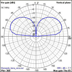
3. Monopole with one radial or counterpoise.
Observing the previous analysis, one can conclude that it should be of interest to improve the electrical conductivity of the ground plane to avoid distortions in the radiation pattern and a loss of eficiency. This can be achieved using radials or counterpoises. Using the name of radial or counterpoise has lead to controversy, deeply studied by L.B.Cebik (W4RNL).
The following analysis takes into account only one radial or counterpoise, which is the option chosen by several manufacturers of portable vertical HF antennas. Furthermore, we will consider that both the monopole and the counterpoise are very close to the ground.
There are several theories about the optimal length of the radials. The ARRL Antenna Book recommends a minimum length of half the working wavelength. In our experiment we will run an optimization process with 4NEC2 in order to find the optimal length for our counterpoise.
In the 4NEC2 simulation, in order to avoid the counterpoise to be in direct contact with the ground, we will rise the whole structure 0,1 meters above the ground.
3.1. Antenna design.
In 4NEC2, we simulate the monopole along the "Z" axis, perpendicular to the "XY" plane (fig.8).
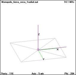
In the simulation, the radial or counterpoise is extended all along the X-axis of the ground plane. We return to the initial value of monopole length calculated in the first analysis (5,16 meters) and run an optimization process with 4NEC2 to find the optimal length of the counterpoise, with the goal of achieving a minimum SWR. The result is a counterpoise of 4,79 meters with an SWR of 1:1,41. Please remember that this solution is only valid for this monopole, at this working frequency and over this type of ground.
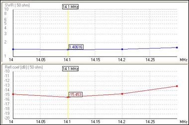
3.2. Simulation results.
After our counterpoise length optimization process, the SWR is around 1:1,4 and almost flat in all the 20 meters band (fig.9).
The radiation pattern is no more omnidirectional: the antenna has more gain in the direction imposed by the counterpoise (the positive "X" axis, in this example).
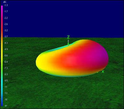
If we analyze the vertical plane of the radiation pattern (fig.11), we can see that the main lobe is located in the general direction of the counterpoise, with a maximum gain of -1,3 dBi at a takeoff angle of 30 degrees. The front/back ratio is 4,6 dB, so it is recommended to install the counterpoise pointing to the remote station azimuth. The radiation efficiency is 16 %
If we compare the results with those of example #2, we see that, using the counterpoise, we have improved the antenna gain in 6,5 dB, having also three times more radiation efficiency. With an adequated counterpoise length we can also achieve the impedance matching in the working band.
It can be concluded that, for a monopole of given length, the use of a single radial or counterpoise of studied length will benefit the overall antenna efficiency and gain in the direction imposed by the counterpoise.
In fact, the counterpoise is another part of the whole antenna, so its length has to be studied to optimize the SWR.
4. Monopole with 4 radials.
In the previous example we have proven that the gain and radiation efficiency of a monopole are improved by means of an unique radial or counterpoise. However, under this condition the monopole is no more an omnidirectional antenna, having more directivity in the direction imposed by the counterpoise. If we want to keep the omnidirectional characteristic, it will be necessary to use at least 4 radials.
4.1. Antenna design.
In 4NEC2, we simulate the monopole along the "Z" axis, perpendicular to the "XY" plane (fig.12). The four radials are laid along each of the semi-axis "+Y", "-Y", "+X"and"-X".
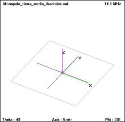
In order to ensure that we have an omnidirectional radiation pattern, the four radials are installed at 90 degrees intervals over the ground plane. In the 4NEC2 simulation, in order to avoid the radials to be in direct contact with the ground, we will rise the whole structure 0,1 meters above ground. The length of the monopole is the same as in the previous examples (5,16 meters) and each radial is 4,79 meters long, as calculated in example #3.
4.2. Simulation results.
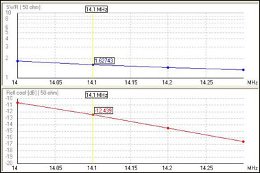
The SWR at the design frequency is 1:1,62, being lower in the higher part of the 20 meters band (fig.13).
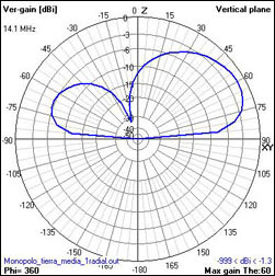
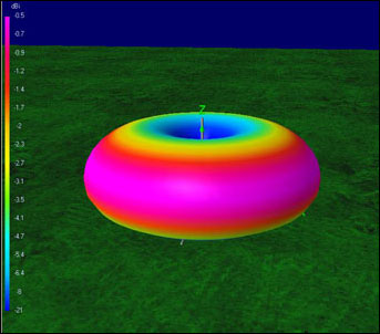
The radiation pattern is again omnidirectional, thanks to the layout of the 4 radials (fig.14).
If we analyze the vertical plane of the radiation pattern (fig.15), we can see that the maximum gain is -0,47 dBi at a takeoff angle of 25 degrees. The radiation efficiency is 27,57 %.
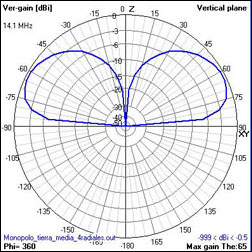
If we compare the results with those of example #3, we achieve an improvement of 0,8 dB in the antenna gain, with the additional advantage of having an omnidirectional radiation pattern. The radiation efficiency is almost twice the previous value.
5. Conclusions.
The table 1 is a summary of the simulations performed with the ideal monopole over perfect ground, the monopole over real average ground and the effects of using one or four radials or counterpoises. It also includes the results obtained simulating several radial configurations up to 256 radials.
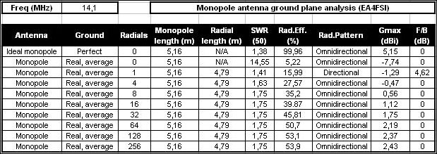
The general conclusions are:
-
The real ground makes the currents flowing out of the antenna to return though a medium of low electric conductivity. The radiation efficiency of the monopole changes to only 5%, the antenna gain is 12 dB worse and the radiation pattern rises, over an average ground. The results are even worse over dry soil. The impedance of the antenna at its feeding point changes, making necessary to design again the antenna length, or to use a matching network or antenna coupler.
-
If an unique radial or counterpoise of adequated length is used, the currents will return to the antenna mostly through this radial/counterpoise and an SWR within limits can be achieved. The radiation efficiency is three times bigger than in the previous case and the antenna gain is 6 dB better. The antena is directive, having its radiation maximum in the azimuth angle imposed by the radial/counterpoise.
-
In order to achieve an omnidirectional radiation pattern, an even number of radials must be used, in a completely simmetrical layout. The higher the number of radials, the bigger the radiation efficiency and antenna gain. Using more than 128 radials will not make further difference. This result coincides with the presented at the ARRL Antenna Book.
|
Ismael Pellejero - EA4FSI |
 EA4FSI Home |
 HF Antennas TOC |
 HF Central |