 EA4FSI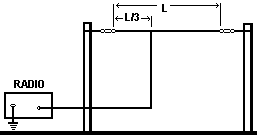
| Type | Horizontal wire antenna |
|---|---|
| Design | REMER |
| Impedance | 50 ohms |
| Modeling | MMANA-GAL |
| Band | Multiband |
 Windom for 20 mWindom_20m.maaWindom for 40 mWindom_40m.maaWindom for 80 mWindom_80m.maaWindom antenna simulation report for 20 m (PDF)Windom_report.pdf
1. Antenna design and modeling
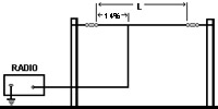
The Windom antenna (Fig. 1) is a horizontal wire antenna consisting of two arms, with a total length calculated as L (m) = 142.5 / f (MHz). The antenna is fed at a point offset from the centre by 14% of its total length. An RF choke is recommended to suppress unwanted common-mode currents on the feed line.
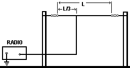
Figure 2 shows the antenna model in MMANA-GAL.

This antenna is resonant at even harmonics of its fundamental frequency.
2. Simulation results.
This section presents the MMANA-GAL simulation results: calculated standing-wave ratios (SWR) and radiation patterns for each band. The example considers an antenna designed for the 40-metre band (7 MHz).
2.1. Standing-wave ratio (SWR)
Figure 3 shows the SWR in the design band (7 MHz), for a characteristic impedance of 50 ohms.
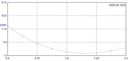
Figure 4 shows the calculated SWR of the same antenna at the first even harmonic (14 MHz).

2.2. Radiation patterns
This section shows the radiation patterns obtained from the MMANA-GAL simulation. We will follow the same example as before, using an antenna designed for the 40-metre band (7 MHz).
Figure 5 shows the radiation pattern in the design band (7 MHz).
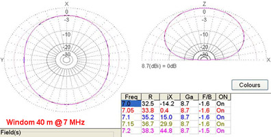
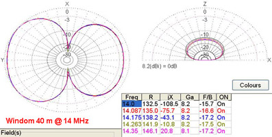
Figure 6 shows the radiation pattern of the same antenna at the first even harmonic (14 MHz).
These simulations are based on an antenna designed for the 40-metre band. The radiation patterns and SWR calculations should be similar for Windom antennas designed to work in other bands. For NVIS operation, the recommended installation height is approximately one-tenth of the operating wavelength above ground (in this case, an antenna tuner may help to match impedances). For DX operation, a greater installation height is recommended.
At its fundamental frequency, the antenna is omnidirectional, with a maximum gain of 8.7 dBi. At even harmonics, its radiation pattern becomes bidirectional, with main lobes perpendicular to the antenna axis and reduced gain.
3. Tools.
Excel spreadsheet to calculate the antenna lengths for each possible working band (frequencies of design).

