 EA4FSI
Summary
Monopole antennas require a ground plane with high electrical conductivity so that their virtual image is correctly formed, allowing current to circulate efficiently for radiation. When a monopole is raised above ground, it is common practice to use an artificial ground plane made up of several radials. In this 4NEC2 analysis, a quarter-wavelength monopole designed for the 2 m band is considered, together with the effects of using four radials at 90° and at 45°.
Originally published on 21 December 2009.
| Frequency | 146 MHz |
|---|---|
| Antenna | ¼-wavelength monopole with 4 radials |
| Height | h = 6 m (3 × λ) |
| Ground | Average real ground |
| Configurations | 4 radials at 90° and 4 radials at 45° |
 Download 4Nec2 model · 90° radialsMonopolo_L4_VHF_tierra_real_Hvar_RH.nec
Download 4Nec2 model · 45° radialsMonopolo_L4_VHF_tierra_real_Hvar_R45.nec
Download 4Nec2 model · 90° radialsMonopolo_L4_VHF_tierra_real_Hvar_RH.nec
Download 4Nec2 model · 45° radialsMonopolo_L4_VHF_tierra_real_Hvar_R45.nec1. Monopole with 4 radials at 90°
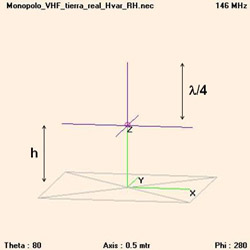
The antenna consists of a quarter-wavelength monopole and four radials of the same length. The radials are parallel to the horizontal plane (90° with respect to the monopole) and are separated by 90° from each other. In the simulation, the antenna is tuned to a centre frequency of 146 MHz and installed at a height of h = 6 metres (3 times the wavelength) above average real ground.
2. Monopole with 4 radials at 45°
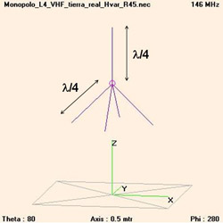
The antenna consists of a quarter-wavelength monopole and four radials of the same length. The radials are inclined 45° with respect to the horizontal plane and are separated by 90° from each other. In the simulation, the antenna is tuned to a centre frequency of 146 MHz and installed at a height of h = 6 metres (3 times the wavelength) above average real ground.
3. Simulation results
| Monopole with 4 radials at 90° | |||
|---|---|---|---|
| Impedance (ohms) | SWR (50 Ω) | Radiation efficiency (%) | Gain (dBi) |
| 24.7 + j8.33 | 2.10 | 53.15 | 5.05 |
| Monopole with 4 radials at 45° | |||
|---|---|---|---|
| Impedance (ohms) | SWR (50 Ω) | Radiation efficiency (%) | Gain (dBi) |
| 60.2 + j41.8 | 2.15 | 61.3 | 6.61 |
When the radials are bent downwards by 45°, the antenna input impedance increases and the SWR becomes slightly worse. However, the radiation efficiency increases from 53.15% to 61.3%, with a 1.5 dB improvement in gain. The 45° radial arrangement also has the additional advantage of requiring less installation space.