 EA4FSI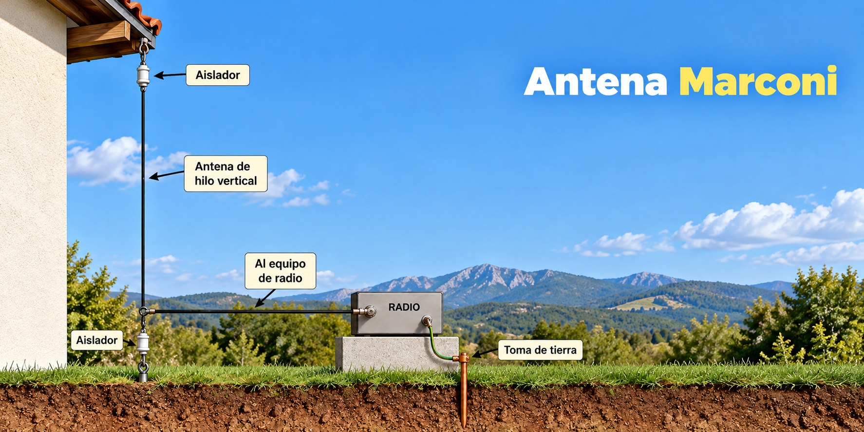
| Type | Vertical wire antenna |
|---|---|
| Design | REMER |
| Impedance | 50 Ω |
| Simulation | MMANA-GAL |
| Band | Multiband |
 Marconi for 20 mMarconi_20m.maaMarconi for 40 mMarconi_40m.maaMarconi for 80 mMarconi_80m.maaMarconi antenna for 20 m — Simulation report (PDF)Marconi_report.pdf
1. Antenna design and modeling
Figure 1 shows the Marconi antenna modeled in MMANA-GAL, oriented along the Z-axis.
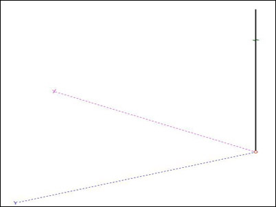
The Marconi antenna consists of a vertical wire approximately one-quarter of the operating wavelength long, fed at its lower end. It requires a highly conductive ground plane. The Marconi radiator is resonant at odd multiples of a quarter wavelength. The wire length is calculated as L (m) = 71.25 / f (MHz).
2. Simulation results
This section presents the MMANA-GAL simulation results, including the calculated standing-wave ratios (SWR) and radiation patterns for each frequency band.
2.1 Standing-wave ratio (SWR)
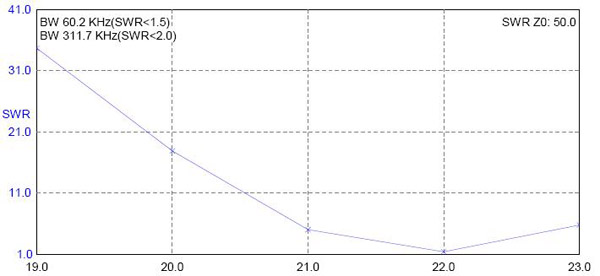
This section presents the simulated SWR at 7 MHz and 21 MHz (the third harmonic) for a Marconi antenna designed for the 40-metre band.
Figure 2 shows the SWR in the design band (7 MHz).
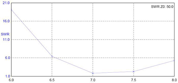
Figure 3 shows the SWR in the third-harmonic band (21 MHz). For SWR < 2, the antenna has a bandwidth of approximately 310 kHz at this harmonic.
2.2 Radiation patterns
This section presents the simulated radiation patterns at 7 MHz and 21 MHz (the third harmonic) for a Marconi antenna designed for the 40-metre band.
Figure 4 shows the radiation pattern in the design band (7 MHz).
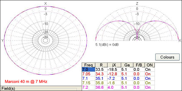
Figure 5 shows the radiation pattern in the third-harmonic band (21 MHz).
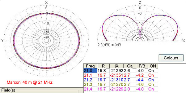
As a vertical antenna, it is not suitable for NVIS operation. At the design frequency, its radiation pattern is omnidirectional, with a gain of approximately 5.13 dBi. At odd harmonics, the elevation pattern becomes distorted and may develop two main lobes, with reduced gain.