 EA4FSI
Warning: This simulation model is provisional and remains under development. The results may be inaccurate or contain errors.

| Type | Broadband inverted-V dipole |
|---|---|
| Manufacturer | Comrod Communications Group |
| Impedance | 50 Ω |
| Simulation | MMANA-GAL |
| Band | 2–88 MHz |

1. Antenna design and simulation.
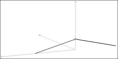
The Comrod AH-52 is a broadband inverted-V dipole with 25 m arms and a loading element at each end. It is suitable for automatic link establishment (ALE) operation.
2. Simulated radiation patterns.
This section presents MMANA-GAL simulations of the antenna's radiation patterns at selected frequencies.
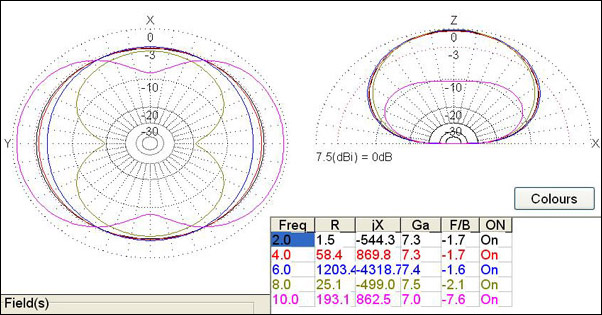
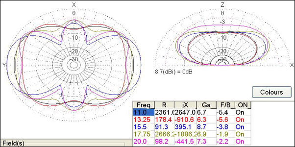
At frequencies up to 10 MHz, the simulated radiation patterns are approximately omnidirectional in azimuth and favour near-vertical incidence skywave (NVIS) propagation. The maximum simulated gain is approximately 7.5 dBi. At 8 MHz, the simulated radiation pattern exhibits a cardioid-like shape. Above 10 MHz, the simulated radiation patterns vary significantly with frequency and may favour longer-distance (DX) communication.