

HF Multiple Dipole Antenna
|
Main → HF Radio Resource Center → HF Antennas → HF Multiple Dipole Antenna |
![]() Este artículo también está disponible en Español (this article is also available in Spanish).
Este artículo también está disponible en Español (this article is also available in Spanish).
![]() Abstract:
Abstract:
This article describes the design and simulation of a multiple dipole antenna for the HF band, using the software MMANA-GAL. The antenna will be designed to operate in the 10, 20, 40 and 80 m bands. The simulations are focused to obtain the impedance and the radiation patterns of the antenna in those bands.
Warning: provisional model in process of modification. The results may be inexact or even contain errors.
 |
Type: Multiple dipole |
| Design: REMER | |
| Impedance: Variable | |
| Simulation: MMANA-GAL | Band: Multiband |
Remarks: Design for the 10-20-40-80 meters band. |
|

Bigote_gato_80-40-20-10m_Sim1.maa
1. Design and antenna modeling.
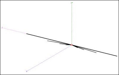
This is a multi-dipole antenna array made of several half-wavelength dipoles cut at lengths corresponding to frequencies of interest. In this design the working bands are 10, 20, 40 and 80 meters. Each arm of each dipole is connected with the arms of the other dipoles in the same side.
2. Simulation results.
In this sections the results of the simulations with MMANA-GAL are shown: calculated standing wave ratios (SWR) and radiation patterns for each band.
2.1 Standing wave ratios (SWR).
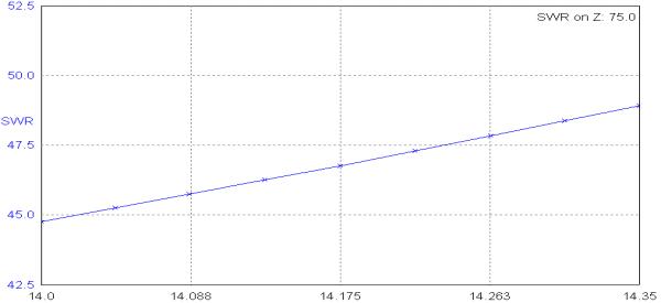
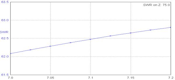
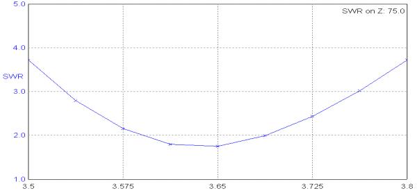
SWR calculations for a characteristic impedance of 75 ohms. The resonance condition for each band may be quite difficult to achieve, so it is recommended to use an antenna tuner. The most adequate transmission line is the 75 ohm twin lead, but you may use also 50 ohms or 75 ohms coaxial cable.
The figs. 2, 3, 4 and 5 show, respectively, the standing wave ratios calculated for the 10 m, 20 m, 40 m and 80 m bands.

2.2. Radiation patterns.
-
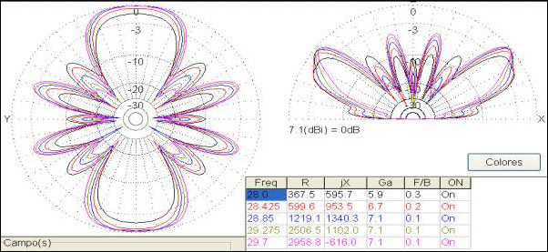
10 m band: the antenna is mainly bidirectional, with two main lobes oriented along the antenna's axis and several secondary perpendicular lobes. Gain around 7 dBi (fig.6).
-
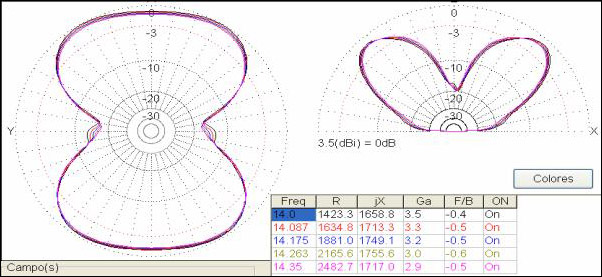
20 m band: bidirectional antenna with main lobes oriented along the antenna's axis, and gain around 3 dBi. Elevation of main lobes is 50 degrees (fig.7).
-
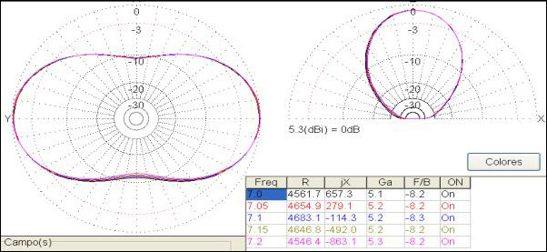
40 m band: slightly bidirectional antenna with main lobes perpendicular to the antenna's axis. Gain around 3 dBi. Suitable for NVIS (fig.8).
-
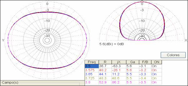
80 m band: omnidirectional antenna, gain over 5,5 dBi, suitable for NVIS (fig.9).
|
Ismael Pellejero - EA4FSI |
 EA4FSI Home |
 HF Antennas TOC |
 HF Central |