
Invelco AT-110 folded dipole antenna
|
Main → HF Radio Resources Center → HF Antennas → Invelco AT-110 |
![]() Este artículo también está disponible en Español (this article is also available in Spanish).
Este artículo también está disponible en Español (this article is also available in Spanish).
![]() Abstract:
Abstract:
Simulations of the INVELCO AT-110 commercial antenna using the 4Nec2 software. The AT-110 is a folded dipole
wideband antenna with a resistive load, able to operate in all the HF band. The simulations are oriented to
the computation of the standing wave ratio and the radiation patterns of the antenna installed in different
configurations.
Table of contents.
1. Introduction.
2. Antenna modeling using 4Nec2.
2.1. Model 1.
2.2. Model 2.
3. Model validation.
3.1. Model 1.
3.1.1. Configuration HM=9, HE=0,5, alpha=72,32º
3.1.2. Configuration HM=12, HE=0,5, alpha=65,75º
3.1.3. Configuration HM=15, HE=0,5, alpha=58,81º
3.1.4. Configuration HM=18, HE=0,5, alpha=51,31º
3.2. Model 2.
3.2.1. Configuration HM=9, HE=0,5, alpha=72,32º
3.2.2. Configuration HM=12, HE=0,5, alpha=65,75º
3.2.3. Configuration HM=15, HE=0,5, alpha=58,81º
3.2.4. Configuration HM=18, HE=0,5, alpha=51,31º
4. 4Nec2 simulation files.
5. Simulation of the AT-110A antenna (model 1).
5.1. Computation of the standing wave ratio (SWR).
5.2. Simulation of radiation patterns.
6. Simulation of the AT-110A antenna (model 2).
6.1. Computation of the standing wave ratio (SWR).
6.2. Simulation of radiation patterns.
7. Conclusions.
7.1. Standing wave ratio (SWR).
7.2. Radiation patterns.
1. Introduction.
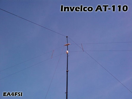
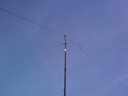
The AT-110 antenna is delivered in three different models (A/B/C), being a folded dipole with resistive load with wideband characteristics in the HF and part of the MF bands. It is a design of the Spanish company "Investigaciones Electrónicas y Comunicaciones (INVELCO)":
According to the manufacturer, the family of AT-110 are designed to work in the frequency range between 1,5 MHz
and 30 MHz, with a maximum power of 150 W or 1,5 kW (depending on the version) and radiation patterns similar to
the presented by an inverted-vee dipole. The fig.1 shows an AT-110A antenna mounted in inverted-vee configuration.
The following sections provide the details of the simulations made with 4Nec2 (based on the NEC-2 algorythm)
and using two different models with the goal of computing the standing wave ratio (SWR) and the radiation patterns
of the antenna in all the working band.

|
Ismael Pellejero - EA4FSI |
 EA4FSI Home |
 HF Antennas |
 HF Central |